
Microgrid Battery Sizing: How to Choose kW, kWh and Outage Duration
Microgrid battery sizing requires balancing power, energy capacity and outage duration. Learn how critical loads, battery reserves, efficiency, degradation and other generation affect the right kW and kWh requirements.
Published · Updated · 11 min read

Microgrid battery sizing is not simply a matter of choosing a large battery. A battery energy storage system has to satisfy two separate requirements: enough power to support the loads that must stay online, and enough stored energy to sustain those loads for the required period while accounting for losses, operating reserves and the contribution of other generation.
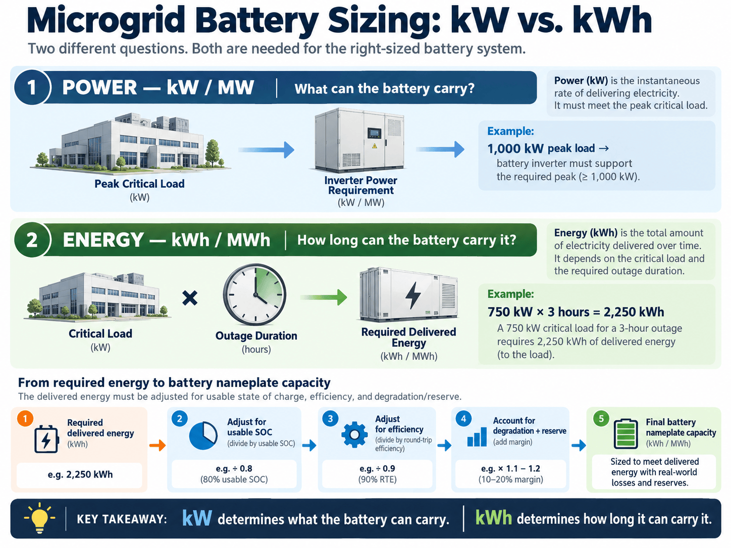
That distinction between power and energy is the starting point for every serious microgrid battery design. A system rated at 1 MW/1 MWh can deliver a large amount of power, but only for a relatively short period. A 250 kW/2 MWh system can run much longer, but it cannot support a 1 MW load by itself.
For resilience projects, the correct battery therefore depends on the critical-load profile, outage duration, solar or generator availability, battery operating limits and the way the microgrid controller is expected to dispatch the system.
What microgrid battery sizing actually means
A battery energy storage system is normally described with at least two ratings:
- Power capacity, measured in kW or MW: how much electrical power the battery and inverter can deliver or absorb at a given moment.
- Energy capacity, measured in kWh or MWh: how much usable energy the battery can store and deliver over time.
Both matter. If the battery has enough energy but not enough inverter power, it cannot carry the required peak load. If it has enough power but too little energy, it will support the load only briefly.
The National Renewable Energy Laboratory’s Battery Storage for Resilience guidance emphasizes three closely related inputs when selecting and sizing resilience resources: the critical load, anticipated outage duration and the value of resilience.
That is why a credible sizing exercise begins with the loads the microgrid must serve rather than with a preferred battery product.
Step 1: Define the critical load
The first question is not “How large should the battery be?” It is “Which loads must remain powered during an outage?”
Critical loads may include:
- Life-safety systems
- Hospital clinical equipment
- Data-center computing and cooling
- Emergency communications
- Water and wastewater pumps
- Security systems
- Selected heating or cooling
- Control, protection and communications equipment required for the microgrid itself
The critical-load profile should ideally be based on interval data or measured feeder loads rather than a percentage of annual energy use. A facility with a 2 MW annual peak may have only 700 kW of truly critical demand, or it may have a 1.8 MW critical process that operates continuously.
Microgrid Media’s guide to how to design a microgrid explains why load analysis and critical-load identification should happen before resource selection.
Step 2: Separate peak power from energy duration
Suppose a facility has 600 kW of critical load and wants four hours of battery-only support.
At a simplified level, the energy requirement is:
600 kW × 4 hours = 2,400 kWh
That suggests a minimum of 2.4 MWh of delivered energy before accounting for battery reserve, conversion losses, degradation, temperature effects or the fact that not all nameplate capacity may be usable.
The power conversion system must also be capable of supporting the instantaneous load. If the critical load can briefly reach 800 kW because a motor, chiller or pump starts, a 600 kW inverter may still be inadequate even though the average four-hour energy calculation appears sufficient.
Step 3: Define the outage duration the project is designed to survive
Outage duration is one of the largest drivers of storage energy capacity.
For short interruptions measured in minutes, the battery may primarily bridge the transition to generators or ride through utility disturbances. For several hours, the battery may serve critical loads directly. For multi-day resilience, batteries are often combined with solar, generators, fuel cells or other replenishing energy resources.
NREL notes that battery storage is well suited to short-duration resilience, while longer outages often require a broader technology mix because stored energy is finite. The U.S. Department of Energy’s resilience resources similarly emphasize evaluating system size and battery dispatch against the site’s actual critical-load requirement.
The practical implication is that a two-hour requirement and a 48-hour requirement are fundamentally different design problems.
Step 4: Account for usable state of charge
Nameplate energy is not always the same as usable energy.
Battery systems may operate between defined state-of-charge limits to protect equipment, preserve life or maintain resilience reserve. A nominal 4 MWh battery might therefore expose less than 4 MWh to routine dispatch.
For resilience projects, the minimum grid-connected state of charge is especially important. If a battery is routinely discharged for peak shaving or energy arbitrage, an outage that begins at the wrong time can arrive when little stored energy remains.
Microgrid Media’s microgrid energy management system guide explains how supervisory controls can maintain battery reserves when resilience takes priority over normal economic dispatch.
Step 5: Include conversion losses
Energy passes through the battery cells, battery-management system, inverter and electrical distribution equipment before reaching the load. Charging and discharging are not perfectly efficient.
A simplified sizing model can divide the required delivered energy by an assumed usable fraction and discharge efficiency:
Required nameplate energy ≈ load energy ÷ usable fraction ÷ discharge efficiency
For illustration only, assume a project needs 2.4 MWh delivered, intends to use 80% of nameplate capacity during the resilience event and assumes 92% discharge-path efficiency:
2.4 MWh ÷ 0.80 ÷ 0.92 ≈ 3.26 MWh
That does not mean every project should purchase a 3.26 MWh battery. The inputs must come from the selected technology, warranties, controls strategy and engineering model. The example simply shows why nameplate capacity usually needs to exceed the raw load-times-hours calculation.
Step 6: Consider battery degradation
Battery capacity can decline over the project life. A system sized only to satisfy the resilience target on commissioning day may fall short later unless degradation is incorporated into the design.
Project teams can address this in several ways, including initial oversizing, augmentation, replacement planning or acceptance of a changing resilience capability. The appropriate choice depends on the warranty, cycling profile, chemistry, operating temperature and financial model.
For a long-lived microgrid, the design question is therefore not only whether the battery can support the required outage today, but whether it can still do so at the defined future performance point.
Step 7: Model solar and generator contribution carefully
A battery rarely needs to be evaluated in isolation if the microgrid contains other resources.
Solar can recharge the battery and serve daytime load, but output depends on weather, season and time of day. A generator can support long outages, but fuel supply, startup reliability, minimum loading and maintenance matter. A fuel cell or combined heat and power system introduces its own operating constraints.
Tools such as NREL’s REopt have been used to evaluate combinations of solar, storage and generators for both economics and resilience. NREL has shown that outage survival can vary depending on the hour and season in which an outage begins, because load and renewable production change through the year.
That is more realistic than sizing a battery against one average day.
Step 8: Size for peak and transient power, not only average load
The inverter and battery must tolerate the power demanded by the islanded system.
Important considerations can include:
- Peak steady-state critical load
- Motor starting current
- Transformer energization
- Large HVAC or pump steps
- Simultaneous load restoration
- Generator synchronization
- Reactive power requirements
- Short-duration overload capability
A battery with sufficient MWh but inadequate MW capability can fail the design objective during a sudden load step.
This is also why battery sizing interacts with microgrid power quality and the behavior of grid-forming inverters during islanded operation.
Step 9: Decide whether the battery must form the grid
If a microgrid contains synchronous generators, those machines may establish voltage and frequency while the battery follows the local grid. In a battery-heavy or renewable-heavy microgrid, the battery inverter may need grid-forming capability.
That function affects inverter controls, power capability, protection and black-start strategy. It does not directly change the number of kWh required to serve a load, but it can change the equipment specification and the way the battery is expected to behave during transitions.
Microgrid Media’s grid-forming versus grid-following inverter guide explains the distinction.
Step 10: Include reserve for contingencies
High-reliability facilities may choose not to size the battery around a single perfect operating case.
Reserve can be used to account for uncertainty such as:
- An outage beginning before the battery reaches its target charge
- Higher-than-forecast critical load
- Lower solar production
- A generator failing to start
- Temporary equipment derating
- Battery degradation
The reserve requirement should be tied to the project’s risk tolerance rather than an arbitrary percentage.
A worked microgrid battery sizing example
Consider a campus with the following simplified resilience target:
- Critical load: 750 kW average
- Short-duration peak: 1,000 kW
- Battery-only support target: 3 hours
- Usable battery fraction: 80%
- Assumed discharge-path efficiency: 92%
Delivered energy needed:
750 kW × 3 hours = 2,250 kWh
Illustrative nameplate energy:
2,250 ÷ 0.80 ÷ 0.92 ≈ 3,057 kWh
The energy side therefore points toward roughly 3.1 MWh before additional contingency, degradation and project-specific margins.
But the inverter also has to support the 1 MW peak. A 750 kW/3.1 MWh battery would not satisfy the stated peak requirement by itself.
This is exactly why kW and kWh must be sized independently.
Battery sizing changes when generators are included
If a generator can reliably start within 60 seconds and carry the long-duration load, the battery may be sized primarily for seamless transition, fast frequency support and short generator-start delays rather than for the entire outage.
At another site, the battery may be intentionally large enough to avoid running generators overnight or to preserve limited fuel. A renewable-heavy system may use the battery to bridge solar variability and maintain enough state of charge to survive nighttime hours.
There is no universal battery-to-load ratio that applies to all microgrids.
How load shedding affects battery size
A resilient microgrid can reduce storage requirements by separating critical and deferrable demand.
If 1.5 MW of total facility demand can be reduced to 650 kW of essential load during an outage, the amount of battery energy required for a given duration can fall dramatically.
That does not mean loads should be classified aggressively simply to reduce battery cost. Critical-load tiers need to reflect actual mission, safety and operational dependencies.
Microgrid Media’s coverage of microgrid resilience during grid outages explains why resource sizing and load prioritization need to be evaluated together.
Why software models are better than a single arithmetic formula
The simple equations in this article are useful for understanding the design logic, but final systems should be evaluated with time-series data and project-specific models.
NREL’s REopt approach evaluates battery dispatch, technology sizing and outage survival using site data. Sandia’s Microgrid Design Toolkit evaluates alternative microgrid designs against objectives such as performance, reliability and cost.
These approaches capture interactions that a single average-load calculation cannot.
Microgrid battery sizing checklist
- Define the exact critical-load profile.
- Identify the highest power the battery must supply.
- Set the required battery-only or total outage duration.
- Determine usable state-of-charge limits.
- Account for conversion losses.
- Model degradation over the required life.
- Include solar, generators and other resources realistically.
- Evaluate seasonal and hourly outage-start conditions.
- Check transient and motor-starting requirements.
- Define grid-forming and black-start requirements.
- Set resilience reserve policy.
- Test the final design during commissioning.
Frequently asked questions
What is the difference between kW and kWh in a microgrid battery?
kW describes power: how much the battery can deliver at a moment. kWh describes energy: how much electricity it can deliver over time. A microgrid battery needs enough of both.
How do you estimate battery size for an outage?
A simplified starting point is critical load multiplied by required hours of support. That result must then be adjusted for usable state of charge, conversion losses, degradation, reserve and the contribution of other generation.
Should battery storage be sized to the entire facility load?
Not necessarily. Resilience projects often distinguish critical from noncritical loads. The correct load basis depends on what the facility must keep operating during the outage.
Can solar reduce the battery size?
Potentially. Solar can serve load and recharge storage during daylight, but the design should model seasonal and weather variability rather than assume nameplate solar production is always available.
Does a microgrid battery need extra capacity for degradation?
Often, yes. If the resilience requirement must still be met years into the project, degradation and the planned augmentation or replacement strategy should be included in the design.
The bottom line
Microgrid battery sizing is a two-dimensional problem: power determines what the battery can carry, while energy determines how long it can carry it.
The correct design starts with measured critical loads and a defined outage objective, then accounts for battery operating limits, losses, degradation, renewable production, generators and resilience reserves.
For preliminary screening, load multiplied by time is useful. For a project that must actually survive an outage, final sizing should be based on time-series modeling and validated against realistic operating scenarios rather than a single rule of thumb.


